A waveform monitor is a sort of "programmable CRT." Its left-to-right scanning pattern is very similar to that of a picture monitor, but we can change the rate of that scanning. The vertical scanning pattern is not our usual top-to-bottom sawtooth, but is a representation of the voltage present at the input terminal - normally 1 volt of video (from the bottom of sync to 100 units of white level). The brighter the video level is, the higher it appears on the face of the waveform monitor screen. We can adjust how sensitive the waveform monitor's amplifiers will be in the vertical dimension (the "gain" of the displayed image).
As well, the frequency response characteristics of the amplifier can be changed so we can see just the luminance, just the chrominance, or both components of the composite video signal. Finally, we can synchronize the waveform monitor's sweep to the video we're looking at, or to an external reference. To do all of this, there are several controls available to us.
Input Controls
|
|
Filtering
There are three possibilities available to us: FLAT, LPASS (also called IRE), and CHROMA. The waveform illustrations are pictures of full field colour bars with the waveform monitor switched to the various filter positions (the following controls' names may vary from one waveform monitor to another, but the principles are the same.
|

|
|
|
|
The Flat position allows us to view luminance and chrominance information - the whole range of frequencies in the composite video signal.
|
The Low Pass (IRE) position passes just luminance information - all the chrominance information has been stripped from the waveform.
|
The Chroma position is the opposite of the Low Pass - the luminance information is now missing, leaving just the chrominance.
|
(courtesy Tektronix)
The waveform monitor has these variations so that we can observe various aspects of the video signal, without others getting in the way. For example, sometimes it is desirable to see just the absolute luminance of a video signal, but the picture may have a lot of highly saturated areas in it. This obscures our analysis of the black and white aspects. In this case, the Low Pass capability of the waveform monitor is used, to get rid of the colour details.
On some more recent units, holding down the filtering switch selects an "alternating" mode. In this position, the Low Pass mode will be turned on for the left side of the monitor display, and the Flat mode will be selected for the right side of the display. The switching between these two modes occurs during the horizontal or vertical sync interval.
Reference
The waveform monitor is normally adjusted to sweep its electron beam in synchronization with the video signal being monitored. This means that we can see lines or fields of video clearly, with no jittering or drift.
Occasionally, we want to see any small amounts of jitter, for example, when "timing" sources to a switcher, so dissolves, wipes and keys can be generated cleanly. In instances such as these, we can arrange to have the waveform monitor locked to an external synchronous reference, usually in the form of an "external sync" signal. This usually comes directly from the sync generator at central racks. The sweep of the waveform monitor will now be locked to the outside, stable reference, and so any instabilities in the signal being monitored will show up as a movement of the waveform. This can be measured and steps can then be taken to deal with it as required. This will be dealt with separately in a later section.
Input Selection
As a convenience to the operator, most waveform monitors come with a switch to select between two different video sources. The switch is usually called an "A/B" switch. On some more recent units, holding down the switch for more than a moment selects a special "alternate" mode where both inputs can be viewed simultaneously on one waveform. The switching between these two inputs occurs during the horizontal or vertical sync interval.
Vertical Adjustments
|
 |
|
Two line display, with GAIN turned on
|
Gain
As mentioned before, the gain of the amplifier has the ability to be varied, like the volume control on an audio amplifier. Obviously, the video signal doesn't get "louder"; instead, it takes up a proportionately greater vertical area of the waveform screen. Usually, the control consists of two parts: a switch to go between a unity (normal calibrated) state, a five times magnification (X5), and a variable (VAR) mode. In unity, the waveform acts normally - one volt of video will usually land between the -40 and 100 markings on the graticule (the lines on the waveform monitor's screen). In the X5 magnify mode, the signal will be five times as high as normal. With the VARiable mode, a GAIN knob comes into play to allow you to vary continuously how large the signal will be displayed on the screen.
This feature is used to measure signals that normally are very small on the screen, for example video noise, hum, or very low video signals.
|
DC Restoration
Video is considered a high frequency alternating current (AC). The video input to a waveform monitor is generally "AC coupled," which means that any direct current (DC) voltage offsets will be eliminated the moment the video enters the unit. This is done so the video signal doesn't go off the top or bottom of the scale (which would be easy, considering that we�re measuring a voltage as small as 1 volt peak-to-peak). This causes a problem, however.
Since the video is AC coupled, the waveform has a tendency to "float" up and down the monitor screen, in an attempt to centre itself within the CRT's face at all times. This is next to useless when trying to measure video levels, since the entire signal will be wobbling up and down the display, making it impossible to take accurate readings. To solve this problem, the waveform monitor has a "DC restorer" built into it. This circuit looks for the sync part of the video signal and freezes the display to it, regardless of what the overall peak-to-peak video level is. It is now a simple matter to use the vertical position knob to position sync and blanking, to be used as a reference for reading video levels. Usually, you should leave the DC restoration ON.
Position
This is a variable control that positions the waveform display up and down on the screen. It is normally adjusted so the sync tip of the video waveform rests at -40 units on the graticule, and the blanking is at 0 units.
Horizontal
|
 |
Sweep
As mentioned earlier, the sweep speed from left-to-right can be varied on a waveform monitor. Normally, we like to view either one or two lines of video, or occasionally two fields, across the waveform monitor screen. The sweep switch is usually labelled 2 LINE and 2 FIELD. Some waveform monitors also have a selection here for 1 FIELD and 1 LINE.
The 1 LINE position gives a fast display of video lines 1, 3, 5, and so on, followed by lines 2, 4, 6 and so on - this is, of course, because the video signal is interlaced. This display is sweeping horizontally at a rate of 15,734 Hz, so you don't see it flicker, and all the lines of a video signal merge into the one displayed.
Two line display |
Two field display |
The 2 LINE position gives a similar display, but since there are two lines visible at any one moment, the display is sweeping at a rate of 7867 Hz (15734 / 2) and shows you lines 1 & 3, 5 & 7, and so on, then 2 & 4, 6 & 8, etcetera.
The 2 FIELD position gives you the first and second fields of a frame of video, with a vertical interval in the middle, about every 30th of a second. This is why you sometimes perceive that a 2 field waveform monitor display is flickering a little.
Magnification
The horizontal sweeps we've just mentioned also can be magnified like that discussed in the vertical section. Generally, this is a two-position switch ON and OFF. The OFF position is self-explanatory.
| Once turned ON, various things are visible. During the 2 LINE display, the magnification is such that you can see 1 microsecond (1 / 1,000,000 second) within one of the wider divisions on the screen (the ones about 1 cm long). This is commonly called "1 microsecond per division (1 :s/div)" and can be used to very accurately measure small areas of the horizontal sync interval, colour burst cycles, and so forth. |
Two line display, magnified
|
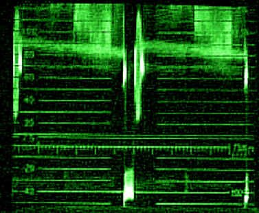
| With a 2 FIELD display, the magnify mode ON gives you one full vertical interval (the one between the two fields mentioned above). This is useful for checking that the vertical sync and equalization pulses are being recorded correctly with helical scan VTRs, checking vertical interval inserted signals, and other critical work in this area of the video signal. |
Two field display, magnified |
Field Selection
As we now know, there are two types of vertical interval (they differ for field one and field two, due to the interlace pattern of NTSC video). There must be a way to select which field we wish to observe (or which vertical interval, when using the horizontal magnify modes). This switch is the FIELD switch and is labelled appropriately with a FLD 1 and FLD 2 position. You can select as desired.
Position
This is a variable control that positions the waveform horizontally. It is used to position the sweep left or right for accurate measurements.
Display
|
 |
Focus
This focuses the CRT beam for optimum definition.
Scale Illumination
This controls the level of graticule illumination.
Intensity
This controls the intensity of the CRT beam. It's like the brightness control on a picture monitor.
Line Selection
|
 |
In addition to all the functions mentioned above, the waveform monitor can display a single particular line of the video signal, in either field, fully, and without interference from adjacent lines. Selecting LINE SELECT enables this feature.
In a 1 LINE or 2 LINE sweep mode, you will be able to see the particular line you selected. On some waveform monitors, the line is indicated by a multiple-position rotary knob with the line numbers on it. On others, the line and field information is actually displayed on the CRT with a built-in character generator. On many units, an external video output at the back allows you to hook up a video monitor that will display a superimposed bright line within the entire picture, showing where you're monitoring.
With these controls, you will be able to pick out any particulars in a composite video signal, and check them in great detail.
Graticules
The NTSC graticule has two main vertical scales. The left side scale is marked in IRE Units and extends from -50 to +120 in 10 unit increments. Black level ("setup") is represented by a dashed line at 7.5 units. There are small +/-2 and +/-4 unit "tick marks" at the bottom centre of the scale, around the -40 units line, for measuring small changes in sync amplitude.
The scale on the right is for measuring depth of modulation and is generally used in transmission environments.
The horizontal reference line is the baseline at 0 IRE. This timing line is 12 divisions long and takes on different timing intervals depending on the sweep rate selected. In 2 LINE, each major division is 10 :s; when magnified, each becomes 1 :s. In 2 FIELD, the scale is not used, since this is mostly a monitoring mode.
When using the waveform monitor with colour bars (or any other video source, for that matter), the sync tip should just be touching the -40 IRE marking. This being so, the 0 IRE baseline corresponds with 0 units of video; 7.5 units of video (setup) should be on its corresponding line. The white flag of colour bars just touches the 100 IRE scale marking.
|
Waveform monitor graticule for NTSC video
|
For a quick reference list of waveform monitor functions, please see the Appendix.
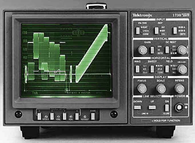
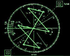
Vectorscopes
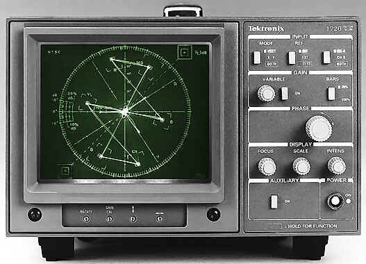
Vectorscope (courtesy Tektronix)
The visual sensation of colour is described in three qualities: luminance, hue and saturation. Luminance is brightness. This is well handled by the luminance portion of NTSC video systems. Chrominance is measured by its hue and amplitude. Hue is the attribute that determines red, blue, green, or any other colour. White, black and grey are not hues. Saturation is the degree to which a colour is diluted by white light to distinguish between vivid and weak shades of the same hue. Vivid red is highly saturated and pink has little saturation. In life, saturation is a product of both luminance and chrominance amplitudes; in colour TV, colour amplitude is measured by chrominance level only.
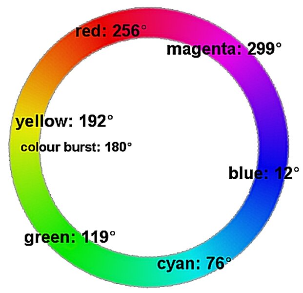
|
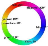
Subcarrier phase colour wheel (click on picture for a bigger view)
|
Colour television review: the hue and colour amplitude information in the colour television system is carried on a single subcarrier frequency: the now familiar 3.579545 MHz. This signal, in modulated form, is called chrominance. The hue information is carried by the subcarrier's phase, and is measurable as being anywhere between 0 and 359 degrees, like the protractor you find in a high school math kit. The colour amplitude information is carried by how high a level the subcarrier has at any given point in the composite video signal. To keep all of this straight, we send a short burst of reference - several cycles of 180 degree pure subcarrier at the start of every line - the colour burst. |
Math protractor
|
From this analysis, it can be seen that the most logical way of looking at colour hue and amplitude is with a circular display. Enter the vectorscope.
A vectorscope is another "free running" CRT, like the waveform monitor, except that both the left-to-right and top-to-bottom directions are left running loose - with some moderating influences. The vectorscope takes the composite video signal, samples the colour burst from it, and uses that as a reference - a continuous sine wave is regenerated from this known quantity. The remainder of the colour information in the signal is decoded in a way similar to a conventional colour monitor. The R-Y decoded output is directed to the vertical deflection circuit, and the B-Y is sent to the horizontal deflection circuit. The combination of these two outputs gives us our familiar vectors.
With the capability of left-to-right (also known as "X" axis) and top-to-bottom (also known as "Y" axis) freedom, many other two-dimensional signals can be measured. Some vectorscopes have an audio input so the left and right channels of a stereo signal can replace the normal X and Y chrominance information, to check amplitude and audio phase.
Input Controls
|
|
Reference
Sometimes it is desirable not to use the colour burst-derived subcarrier reference - when colour timing is being done on various sources feeding a switcher. In this case, the subcarrier reference can be switched from INT to EXT, allowing a separately generated continuous wave subcarrier to be fed to the vectorscope. This signal is usually generated by the station's central sync generator.
A/B
Like the waveform monitor, most vectorscopes can look at two inputs. On some devices, you can view both signals simultaneously. This condition usually requires the external source of stable subcarrier discussed above.
Gain
|
 |
Variable
This is a switch/knob combination that allows you to vary the length of the vectors on the display. This is useful for accurate setting of colour bars and external subcarrier measurements for timing purposes.
Phase
|
 |
This is a continuously variable control with 360 degree range to set the phase of the decoder reference. The result of this is that you can turn the vectors around the screen at any degree that you want. The usual setting is such that colour burst is at 180 degrees, directly to the left (9 o�clock), on the display.
Display
|
 |
Focus
This control adjusts the focus of the CRT electron beam for the finest picture.
Scale Illumination
This adjusts the intensity of the lamps that illuminate the graticule.
Intensity
The brightness of the CRT beam, and thus the display, is adjusted with this control.
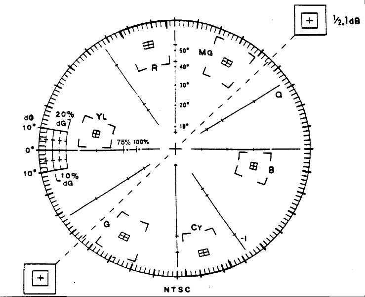
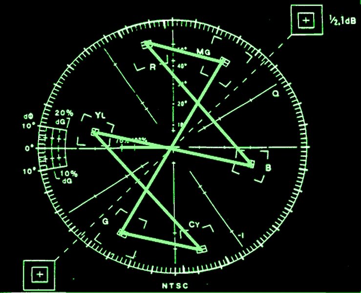
Graticules
On the vectorscope scale, the polar display permits measurements of hue by the relative position of the vectors around the display with respect to the colour burst. Relative amplitude of chrominance is shown as the displacement from the centre towards the colour point.
Each colour bar chrominance vector terminates in a system of targets in the form of two boxes - a small one inside a large one. The dimensions of the large box represent +/- 10 degrees centred on the exact chrominance phase, and +/- 20% of chrominance amplitude centred around 100% of standard amplitude. The smaller boxes represent +/- 2.5 degrees and +/- 2.5 IRE units. The idea, of course, is to get the vectors of each colour bar as closely as possible into the little boxes. This is done by adjusting the phase and chroma level controls of the device being monitored (VTR, camera encoder, etc.)
As mentioned before, vectorscopes also can be used to make stereo audio phase measurements. When identical signals of equal amplitude are input, the resulting display will be a Lissajous pattern. If there is no phase error between them, the display will be a diagonal line, at a 45 degree angle running from the bottom left to the upper right of the display. When the signals are not in phase, the pattern will be displayed as an ellipse. When the audio signals are 90 degrees out of phase, the pattern is a circle. At 180 degrees out of phase, the display is again a straight line, but the axis of the display is rotated by 90 degrees - it runs from the upper left to the bottom right.
|
Vectorscope graticule for NTSC video (click on picture for a bigger view)
|
Detail of vectorscope colour bar "target" (click on picture for a bigger view)
|
What proper colour bars look like on a vectorscope (click on picture for a bigger view) |
For a quick reference list of vectorscope functions, please see the Appendix.
Timing
As each video source enters a switcher, its video scan must begin and end at precisely the same moment as any other source. If this is not so, you will get a horizontal shift in the picture, as you try to dissolve or wipe from one source to another. This is because the switcher holds the horizontal sync of the first source until the transition is completed; the jump happens as the switcher cuts to the second horizontal sync signal. If the scans begin at vastly different times, some switchers will simply cut from one source to another; they won't allow the dissolve or wipe to take place at all. This alignment of the scanning rates is called "horizontal" or "H" timing, as it affects the horizontal position of one image relative to others.
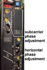
In addition, because we are working in colour television signals, each source's colour burst must be "in phase" with every other source's burst. If this is not the case, you will get a 'colour shift' when dissolving, e.g., a scene will go from normal to 'purple' or 'green'. This is called "system phase" or "subcarrier phase," but not "burst phase" (which is the local colour "hue" set-up at the VTR processing amplifier or TBC).
Frame Synchronizers - A Side Note
Much of our new technology involves sources that are "free running"; that is, their scans bear no relationship to our own house sync generator. They're video, to be sure, but the horizontal and vertical synchronization pulses can begin anywhere relative to other equipment within a television station. Such a source taken to air directly would be objectionably shifted horizontally (and possibly vertically as well). Our modern solution to this modern technology is the frame synchronizer. This box takes an entire frame of the remote source's video (whenever it may have started its own scan), and stores it in computer memory. It then releases it when cued by the in-house sync generator�s next vertical interval. This makes satellite, microwave, laser link, and domestic camcorder sources available to us.
Why not use frame synchronizers for every source in the building, at every input to every switcher? It's expensive. Also, every time you feed a video signal through such a device, it is converted to digital form, and then back to analog again. This does involve some degradation, no matter what the manufacturer's specifications say. Also, this process results in the video being delayed by one frame (about 1/30 second) with respect to the audio, which has not been through any processing. While a one frame delay may not be that noticeable, doing this two or three times results in unacceptable video to audio time shifts.
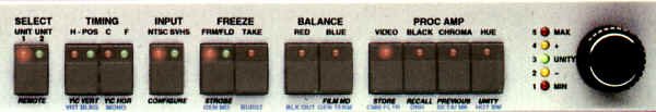
TBC Front Panel, showing Timing controls (horizontal and subcarrier) and processing amplifier adjustments (courtesy DPS)
How To Time A Video Source
Now that you've been convinced there's no free lunch with this timing business, here's how to do it.
The TD (Technical Director) has access to a waveform monitor and a vectorscope. Both devices are "externally synchronized" for this operation, so they have a constant signal to which they can refer. What this means is that the waveform monitor's EXT/INT switch is set to EXT (with a suitable external sync source, from the station's sync generator). The vectorscope's EXT CW selection is chosen (with a suitable source of continuous wave subcarrier, again from the sync generator).
The waveform and vectorscope should be set up to monitor either the switcher's program output bus, with any processing amplifier bypassed (if the switcher is not live on air, of course), or the switcher's preview bus. These are usually pre-wired by the engineers to come up as the "A" side and "B" side of the waveform / vectorscope selection switches.
Once this condition is met, set the waveform to 1 :s/div, so an expanded horizontal sync pulse is in view. The vectorscope's burst should be set to 180 degrees (straight to the left), based on "BLACK" as selected by the relevant switcher bus. If desired for easier viewing, the vectorscope's gain can be increased.
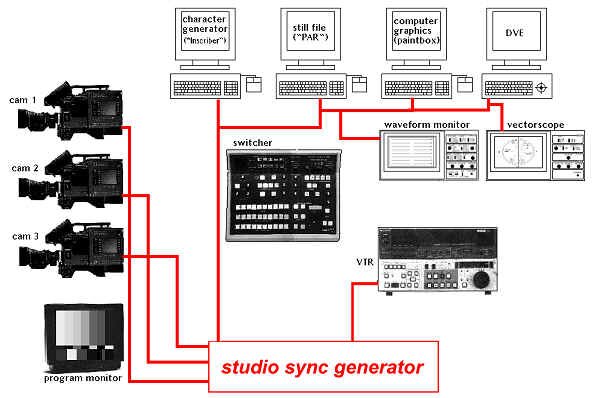
Typical studio configuration, showing distribution of sync pulses to various pieces of equipment
|
To check horizontal timing at a VTR, the TD will switch between BLACK and the source in question. The VTR operator is 'talked through' adjustments of his horizontal timing pot so the TD sees no horizontal shift between the two, while viewing the expanded horizontal interval on the waveform monitor. As the actual length of the horizontal interval may vary slightly from source to source, use the right edge of sync as your reference. This is where each video line's blanking starts.
To check subcarrier timing, the TD will select the source in question, after having set the vectorscope's burst phase to 180 degrees on BLACK. He will 'talk through' to the VTR operator who is adjusting the colour subcarrier pot, until the new source's subcarrier phase is also at 180 degrees.
The VTR is now timed to the switcher and anything played back from that machine can be dissolved or wiped. It also will have the correct colour phase. If you bypassed your processing amplifier because you were using the output bus of your switcher, don't forget to turn it back on.
Cameras and other timing-dependant sources can be set up similarly. This entire operation should take only a couple of minutes at most, and makes for beautiful pictures.
|
Timing controls on a camera
|
|
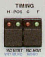
Timing controls on TBC
|
|
Typical off-air vertical interval, showing insertions
|
Vertical Interval Insertions
As already discussed, the vertical interval goes through several manoeuvres to ensure that the horizontal synchronization does not go out of alignment with regard to the interlace pattern of NTSC television. Specifically, there are two sets of equalizing pulses generated during the vertical interval, along with the vertical sync pulse interval itself.
But, these special pulses only take up 9 horizontal lines' worth of time; active video doesn't start until much later - on line 22. In the meantime, there are several lines of just blanking and sync. They could be used for special purposes and, in fact, they are.
|
Teletext in general is a system by which textual information is encoded as video, sent in the vertical interval of a television signal, and then decoded at the receiving end of the transmission. Teletext at present uses lines 14, 15 and 16; some alternatives also use lines 17 and 18.
NABTS stands for North American Broadcast Teletext Specification, and is based on the NAPLPS protocol. NABTS is actually broken down into two parts - NAPLPS, which sends pages (screens of information) as streams of eight-bit bytes, and the data mechanism to put the streams on a TV channel. It's certainly possible to put something other than NAPLPS in such a "data channel."
VITS stands for Vertical Interval Test Signal. This is a general term incorporating test signals inserted within lines 10 through 21. These signals vary according to the needs of the television station, and the country of transmission. In the United States for example, a reduced multiburst is required on line 17, field 1; colour bars on line 17, field 2; and FCC composite on line 18, fields 1 and 2.
VIRS stands for Vertical Interval Reference Signal. It consists of a 70 unit IRE signal modulated with subcarrier of the same level and phase as colour burst, with 50 and 7.5 unit IRE level signals. It is normally used for either manual or automatic adjustment of chrominance gain and phase, luminance and setup parameters of a video signal. The modulated 70 unit signal is of average chrominance phase, at average Caucasian skin-tone luminance level. The 50 unit IRE signal represents an average picture luminance level, and the 7.5 unit IRE pedestal is used for picture black level setup. VIRS is normally found on line 19, both fields.
Some television sets can make use of this signal to align themselves automatically for the best picture quality. For this to work, each source is supposed to generate its own VIRS signal, and shouldn't be stripped out or re-generated later - the idea being that, as you go from source to source, the viewing or monitoring system adjusts for each one. This concept has never really caught on, however.
GCR - Ghost Cancelling Reference - is a relatively new signal transmitted on line 19 of some television stations. It�s a sweep in frequency from 0 Hz to 4.2 MHz, occurring over one video line. It's only useable by new television receivers that have ghost cancelling ability. The GCR is transmitted with the regular TV picture and is compared to a clean version that resides in the television set. Any differences found are used to tune out ghosts in the received transmission.
VITC is Vertical Interval Time Code. As well as being recorded on videotape as audio in a linear fashion, time code also can be converted to video information. Many time code readers and generators are capable of reading and writing this data in the vertical interval on a given line (19 is often used).
Closed Captioning is a method by which text information can be transmitted to individuals who have a special decoding box, or any recently manufactured television set measuring 14" or more in screen size. This is used to transmit locally displayed captions for the hearing impaired.
The captioning data signal is contained in the television signal vertical interval on line 21, field 1. The signal must be transmitted from a station intact and on the right line and field, or consumer decoders will not operate. The captioning data signal is as much a part of the program as the video and audio portions.
| Finally, there�s nothing stopping you from taking over several lines of the vertical interval and making your own "mini-picture" in that space. Usually, readable text is inserted in the space to ID the source from which it�s being sent. Special generators are available for this purpose. |
Vertical interval text (courtesy QSi Systems)
|
Things To Think About
We need a way to view our video information other than monitors, so that we may maintain quality control over our television signal.
Waveform monitors can display luminance and chrominance information, showing it to us in various ways and in various detail.
Vectorscopes can display chrominance information - hue (colour phase) and saturation, again, in various ways.
Explore the controls of each of these devices, and be at ease with them.
Sources need to be timed into a switcher so that we can do synchronous transitions between them. Waveform monitors and vectorscopes can be used to facilitate this timing. Be comfortable with how to do this.
Various signals can be inserted in the vertical interval, and can be seen on the waveform monitor and vectorscope. Become acquainted with some of the more common ones - befriend them.