


 |


"I have a friend who just got back from the Soviet Union...the first question he was asked was if we had exploding television sets. You see, they have a problem...many are exploding. They assumed we must be having problems with them, too."
-- Victor Belenko, MiG-25 pilot who defected in 1976
Black and White Picture Tubes
Typical black and white picture tube (courtesy Broadcast Engineering)
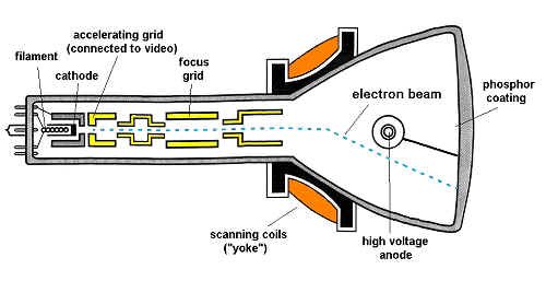
The majority of television sets use a picture tube, ranging in size from 1 to 40 inches, measured diagonally. At its narrow end, a typical picture tube used in black-and-white monitors contains an electron gun. Within the gun is a control electrode, connected to the video signal, which accelerates and slows down the electron beam to recreate the brighter and darker portions of the image. For the electron beam to operate like this, the tube must have a high vacuum, and be capable of withstanding the pressure of the outside air.
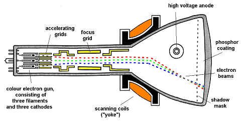
The focusing coil or grid, within the electron gun, keeps the electron beam narrow, so when it strikes the faceplate at the wide end of the tube, it is still very small. The scanning coils are located where the tube just begins to expand in size. Rapidly reversing currents, produced by the monitor's electronics, are passed through these coils, producing magnetic fields that deflect the electron beam in the now familiar interlaced pattern.
|
Inside the wide end of the tube is the viewing screen. It consists of two coatings. The first, deposited on the inner surface of the glass face, is a material known as a phosphor. The second is a thin coating of aluminum on the phosphor. The phosphor is a complex compound, typically containing oxides of sulphur and zinc, that glows with a bluish white light when struck by high-energy electrons.
To assure that the electrons in the beam have enough energy, a high voltage (typically 10,000 to 20,000 volts) is applied to the picture tube between the electron gun and the aluminum coating. This positive high voltage at the screen end of the tube attracts the negative electrons; when these electrons hit the screen, they produce a spot of light of variable brilliance. To reduce the hazard of electric shock, the high-voltage supply of the monitor is designed to operate at a low current, a few thousandths of an ampere at most.
|
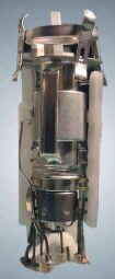
Black and white picture tube electron gun
|
Colour Picture Tubes
|
Colour monitor phosphors
|
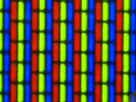
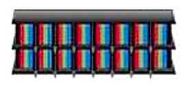
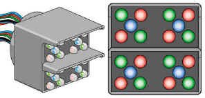
If you look at the screen of a colour monitor through a magnifying glass, you can see it's made up of many tiny dots (or line segments in more recent tubes) that glow with red, green, and blue light. |
|

Dot phosphor (sometimes called delta gun) colour CRT (courtesy Broadcast Engineering) (click on picture for a bigger view)
|
These tubes have one of two basic fluorescent screen structures, known as the dot phosphor, and the strip phosphor or inline Trinitron. In both cases, chemical compounds (phosphors) that convert electron-beam energy into light of the additive primary colours (red, green, blue), are deposited on the inner face of the glass picture tube in precision arrangements in dots or stripes of alternating colours. |
Inline (or Trinitron) colour CRT (courtesy Broadcast Engineering) (click on picture for a bigger view)
|
Typical colour television picture tube
|
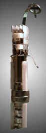
Colour picture tube electron gun assembly
|
At the rear of the picture tube is the electron gun, which produces three separate beams of electrons. These three beams hit the coloured dots, and the tube is so designed that each beam can hit dots of only one colour; a mask prevents each beam from striking the others' colour dots.
|
Shadow mask (detail)
|
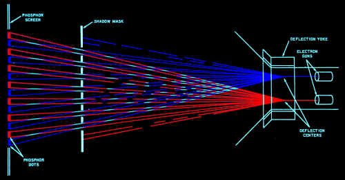
Electron gun deflection and masking
Because the coloured dots are so small that they cannot be seen separately by the viewer, the effect is three superimposed images in the primary colours. By adjusting the strength of the respective beams of electrons, the relative brightness of the image produced by each can be changed.
Flat Screen Displays
The ultimate television set will hang on the living room wall like a picture, and be only a few inches thick.
LCDs
One smaller but proven technology is the liquid crystal display (LCD), which has produced pocket-size portable TV sets with up to 4-inch diagonal screens. While screen diagonals up to 12 inches and more are being produced for such applications as laptop computer screens, none have the brightness, resolution, or contrast range of a direct-view picture tube.
One of the reason LCD displays have not grown to gargantuan proportions is because each little pixel in an LCD display is turned on and off by a very small transistor. The problem is that it�s really hard to "grow" large arrays of transistors in anything other than very, very clean rooms - and even then, there are still flaws, which mean you have to throw the whole thing out and start again (you can�t repair a single pixel. Sorry.)
Plasmatron
To try and address the "impurity" problem, engineers have designed another type of large screen. It still uses liquid crystal pixels, but the switch that actually turns them on and off is a gas discharge.
That sounds complicated, but here�s a common reference point: neon signs are gas discharge displays, too. They have an electrode at each end (called the anode and cathode) and some gas in the tube that transfers electrons easily, and, in the case of your local pub�s signage, also glows brightly when you do this trick.
The inventors put the "neon tube" part of the structure at the bottom of a sandwich, right above a source of "back light" (so we can see the final picture) - see the illustration on this page. Each "run" of anode and cathode electrodes makes up one television scan line. Above the discharge is an insulator to keep the high voltage out of the way of the liquid crystal area. The liquid crystal layer, in turn, gets activated by the discharge below it. It lets light into the colour filters which finally make up our colour picture. The display isn�t "scanned" in the traditional sense - each line lights up in its entirety. Lines are sequenced from top to bottom, and there�s a frame buffer in the Plasmatron system, so the sequencing isn�t interlaced, either.
|
Plasmatron structure
|
|
Gas plasma display
|
Gas Plasma Displays
Differing somewhat from the Plasmatron, these units don't use liquid crystals to turn on their individual pixels. Two channels of gas discharge "tubes", etched into two plates of glass are laid on top of one another, and perpendicular to each other. The intersection of the two channel layers creates the picture elements. Each one of these pixels, in turn, has electrodes imbedded into it, so every spot is digitally addressable. On top of this matrix are red, green and blue phosphors to generate colours. There is no back light needed in this system.
|
Trini-Lites, Diamond Vision, and Bunches of Light Bulbs
| At the other end of the scale, very large flat screens have been built for installation at large athletic parks, where they serve as giant scoreboards or huge television screens. The largest such screen was built by Sony at the Tsukuba Expo '85 in Japan. Using individual triads of red, green and blue TriniLites - colour phosphors arrayed together inside a cell - the screen stood 14 stories high, had more than 10,000 square feet of luminous surface (82 X 131 feet), and could easily be seen by 50,000 viewers. The scoreboard at Toronto's SkyDome is of similar construction. |
Trini-lite
|
|
Diamondvision screen (detail)
|
Examples of other "large screen" displays can be seen. A system called Diamond Vision (an array of high-intensity illuminators) produces a very bright, high contrast, reasonable resolution display - check out the units in the major financial district, displaying the latest stocks and news headlines. Often you�ll see these at large rock concerts, too. A very simple, monochrome system is the Pixelboard device - it�s a big array of light bulbs under computer control. They also make colour versions using - you guessed it - an array of red, green, and blue light bulbs. |
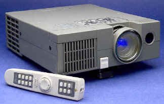
Projection Television Systems
Larger television images can be achieved using a variety of projection systems that are designed for home or professional environments.
|
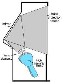
Internal reflection home projection TV
|
Internal Reflection
Home projection TV systems are usually mounted within an enclosed cabinet, with screens ranging from 40 to 50 inches diagonally. The image comes from three high brightness CRTs, each providing a primary colour. These are projected through a folded mirror system, onto the rear of a translucent screen.
|
Front Projection
Larger screens normally employ front projection, using either CRTs, light valves, LCDs or DLP (digital light processing) techniques, and can produce television images on theatre-size screens.
CRT
CRT projection systems employ three high-intensity cathode ray tubes, with a focusing lens in front of each one. The three images converge on a screen at some distance (invariably passing through the smoky environs of your local tavern en route). Nothing fancy here, and it works fine, as long as the systems are maintained from time to time to ensure that the convergence is still accurate, and none of the tubes are smearing their image.
|
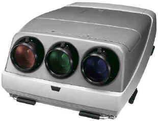
CRT projection system
|
|
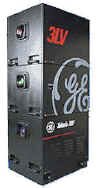
Light valve (G.E. Talaria) projector
|
Light Valves
In one type of projector used in theatres, the scanning pattern is produced by an electron beam on a thin film of oil. This serves as a light valve through which light from a powerful lamp (via a mirrored surface under the oil) is passed to the screen. Three such valves in one projector, superimposed, are used to produce colour pictures.
|
LCDs
These projectors are becoming very popular with the maturity of high density liquid crystal displays. The LCDs are backlit with a strong metal halide projection lamp and, via a standard lens system, the images are projected on a screen.
|
LCD projector
|
|
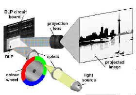
DLP one-chip system (the three chip system looks very similar to a standard television camera prism colour separating system) (courtesy Texas Instruments)
|
DLP
This is a relatively new technology, involving an array of little tiny mirrors, all separately addressable, fitting in a space of less than 2 centimetres across. The mirrors reflect a high intensity light source and, by tilting 10E back and forth, they allow light to reach a projection screen (or not.) The mosaic of all these tilted and non-tilted mirrors creates the picture on the screen. There have been systems developed using one, two or three DLP devices.
The one and two chip systems use a colour wheel to produce the full spectrum - each colour channel�s information is sent to the DLP in turn, in synchronization with the colour wheel�s revolutions. In this way, the system projects red, green, and blue information once for each television field. If you wave your hand in front of this projection or move your eyes too quickly, you�ll see the individual R, G, and B components. The three chip version uses a colour splitting prism similar to that used in a colour television camera, so, while the cost is greater, the "breakup" problem is no longer an issue.
|
Electron microscope photograph of DLP mirrors (some tilted) and mirror actuating mechanism (courtesy Texas Instruments)
|
Image Light Amplifier (ILA)
Image light amplifier systems use a special block consisting of a transparent conductive electrode on which the source's image is projected (from a high resolution CRT.) The voltage output from this electrode is in direct proportion to the light and dark areas of the scene. This output, in turn, is fed to a liquid crystal layer which reproduces the image. A high intensity lamp shines on the liquid crystal, and reflects back, via a mirror and projection lens, to the projection screen. This system doesn't require a high-output CRT, since the high levels of light are created by the projection lamp. Three channels of this are used in colour projection systems of this type. Because the system isn't "pixel" based, it can be used for any type of video system, including NTSC, computer display, and HDTV.
|
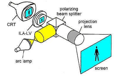
Image light amplifier optic channel (courtesy Hughes-JVC)
|
|
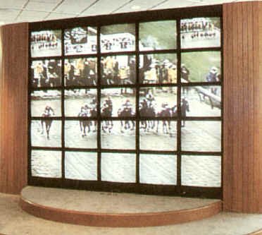
Videowall (courtesy Electrosonic)
|
Videowalls
So-called "videowalls" are nothing more than several monitors arranged in a grid, each displaying only a portion of the complete television picture. Usually the displays are 25" to 27" RGB displays, although occasionally they are as large as 43" each. Sophisticated computer control and digitizing hardware permit the proper part of the television picture to be displayed on the corresponding monitor.
|
How To Line Up A Colour Monitor
A colour monitor is a display device that sends information to the eye - an eye that is very sensitive to changes in brightness, colour and hue. A properly aligned colour monitor can be as important a piece of test equipment as a waveform monitor or vectorscope.
Common mythology insists that colour monitors are unreliable and drift. While it's true that a monitor requires more operational alignment and periodic maintenance than other equipment, this alignment is very straightforward once understood.
But let it be said here and now - colour monitors can faithfully depict the quality of the pictures in a system, if and only if:
 |
the viewing conditions are correct, |
|
the video system feeding it is correct, and |
|
the monitors have been correctly aligned. |
Philosophy of Television Reproduction
The NTSC system is designed to reproduce any scene as if it was illuminated by daylight, regardless of how it was actually lit. A white object in the scene, with a properly white-balanced camera, will register on a correct monitor as 6500 degrees Kelvin (daylight colour temperature). Therefore, all monitors should be lined up to reproduce this "reference white."
Viewing Environments
In the home, the typical television set: emits some light of its own; occupies a narrow segment of the viewer's field of vision; is illuminated by daylight and living room lamps; and sits in often colourful surroundings, with the lights down low. In other words, it exists in a non-critical, but pleasant viewing arrangement. The home viewer adjusts to gradual changes in familiar objects and colours as long as the rest of the scene is in colour context, and will accept a range of somewhat desaturated colours as "white."
But we can't get away with this in broadcast television. An ideal viewing environment for us should have:
|
"the observer seated 4 to 6 monitor screen heights distant and +/- 30 degrees from the monitor screen perpendicular |
|
a `surround' (mask around the monitor) having a colour temperature of 6500 degrees Kelvin and a luminance of 3 foot lamberts; taking up an area eight times the area of the monitor screen. Where several monitors are mounted together, the total surround area should be no less than four times the total monitor screen area. |
|
the viewing room decor and production surfaces giving a generally neutral matte impression without dominant colour. Ambient light on the monitors should be low. Specular reflections on the monitor faces must be avoided. The light sources in the room should have a colour temperature similar to the monitor reference white (again, 6500 degrees Kelvin)."1 |
And to throw another wrench into it, apparently there are presently no reference white standards for domestic television receivers. The two predominant reference white factory calibrations are 6500 K and 9300 K. Probably the average home receiver is set somewhere between these two values, but closer to the higher colour temperature, i.e. more of a bluish white compared to a professional colour monitor.
The problems that come with less than ideal viewing conditions are many. If the observer is seated farther away from the monitor than recommended distances, too much of the surrounding area will be taken into account when judging brightness and colour of the television picture. If seated too close, he/she will eventually suffer from eyestrain.
If the surround is not of neutral colour, the monitors will appear to display the complementary colour. If you're painting a camera in this non-neutral environment, it will be balanced to display a visual match with the area surrounding the monitor. Consequently, the colour balance of the shot for everyone else who views it will be altered, regardless of their viewing conditions. For example, if a monitor bay is flooded with pink gel (as a cosmetic background for a shot) you can be assured that the monitors within that bay will appear decidedly green. They will also probably be of lower contrast due to the amount of light spilled on them.
How To Line It Up
Having shown why even a correctly aligned monitor will frequently not appear as it should, here's one recommended procedure for lining them up. It is suggested that colour monitors be checked and adjusted every three to five days, although some procedures can be done less often.
To do this lineup, you'll need two things:
| 1) some test signals (colour bars, grating and black, maybe a window and multiburst, too) that are routed to the monitor in the same fashion as the rest of the signals you'll be sending to it, and... |
Signal test generator (Courtesy Leader)
|
2) your eyes.
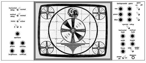
Typical broadcast colour monitor line up controls (click on the picture for a bigger view)
To begin, ensure that the monitor has been on for at least a half hour (preferably an hour). The room ambient lighting should be the same as when the monitor is in normal use. All controls should be in their preset and/or central positions.
One more point: all monitors should be CLEAN. Be sure that all CRT faces have been wiped clean, and are not crusty with dust first; you may find your colour woes can be solved with a little glass cleaner and some elbow grease.
|
Purity error
|
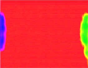
Purity
A lack of purity manifests itself by colours that are not the same from one side or corner of the picture to another. It shouldn't have to be checked more than once a month, unless stray magnetic forces have accidentally come near the monitor.
Turn off the green and blue beams, leaving only the red. Turn the contrast control to minimum and increase the brightness until a medium bright red raster appears. Look for a uniform colour. If you find a problem, use the degausser switch on the monitor. If you still don't have good results, be certain that no stray magnetic fields are near the monitor, e.g., an audio speaker.
|
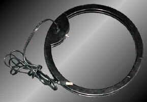
Degaussing coil
|
The internal degaussing system usually works fine, unless the cabinet itself has become magnetized. If you must use a degaussing coil, here's how. Remove your watch and other magnetically sensitive jewellery and adornments (finger rings, earrings, and other body piercings will probably be okay). Hold the coil about an inch away from the picture tube and/or cabinet. Move the coil in a slow circular motion parallel to the monitor for about 3 to 5 seconds. Back away about 6 feet and turn off the coil while it is perpendicular to the picture tube.
DON'T Try This At Home!
DON'T put your stereo speakers, fridge magnets, and similar things on the front face of (or even near) your colour television set! You�ll get purity problems for sure! What�s worse, the purity yuckiness won�t go away even after you remove the magnet. So don�t do it, okay? If you screwed up your set, you�ll probably have to use a degaussing coil to fix it - ask your local engineer really nicely and he or she may let you borrow theirs (but, you�ll have to �fess up to your crime, first.)
You can, if you�re curious, put a magnet on a black and white TV set and watch the scan lines get freaked out (�psychedelic � and cheap Friday night entertainment.)
Scan Size
Underscan should be used on all "source" generators such as cameras and VTRs where checking of picture impairments is vital. Normal scan should be used elsewhere (including the program monitor).
Normal scan should be adjusted so the four corners of the picture are not visible and the safe action area is just visible. This represents overscan of about 5%. To achieve this, standard grating pattern signal is put into the monitor and the height and width controls are adjusted so 12 vertical spaces and 15 horizontal spaces (not lines) are visible. With colour bars as the source, slightly more than � a bar width should be seen on either side of the screen.
|
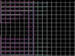
Grating Pattern
|
|
Geometry error
|
Geometry and Aspect Ratio
Geometry is the monitor's ability to scan evenly from left to right and top to bottom. This can be seen by using the standard grating pattern and looking at the green beam only. The pin cushion and scan linearity controls should be adjusted so the picture appears without distortions when seen from normal viewing distances (4 to 6 picture heights, remember?).
|
Focus
This is electronic beam focus (the narrowness of the beam) and should be adjusted for best picture resolution in the brightest and central areas of the picture, without any noticeable loss of definition in the corners.
|
Soft focus
|
|
Convergence error
|
Convergence
While looking at the standard grating signal, the white lines should not diverge into their separate colours anywhere on the screen. This is similar to registration in cameras, except at the monitor.
|
Aperture Correction
This test requires a generator-produced multiburst test signal, not prerecorded and played back from tape. The aperture control corrects for high frequency losses due to cable length, and guarantees that the luminance section of the monitor has flat frequency response. This is rather hard to tell with the naked eye; the best method is to have engineering use an oscilloscope to check the luminance amplifier. The practised eye may be able to set this properly by watching the multiburst signal with the monitor in black and white mode.
|
Multiburst
|
Colour Saturation/Hue/Brightness/Colour Temperature/Grey Scale Tracking
Initial Adjustments
Switch the monitor to the SETUP position. In this mode, the vertical scan is collapsed. Adjust the red, green and blue SCREEN controls so the signals are barely visible. You can do this by only having one of the screens on at once, adjusting it, moving to the next one, etc. These adjustments are only preliminary and will be modified later to achieve correct grey scale tracking.
|
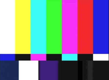
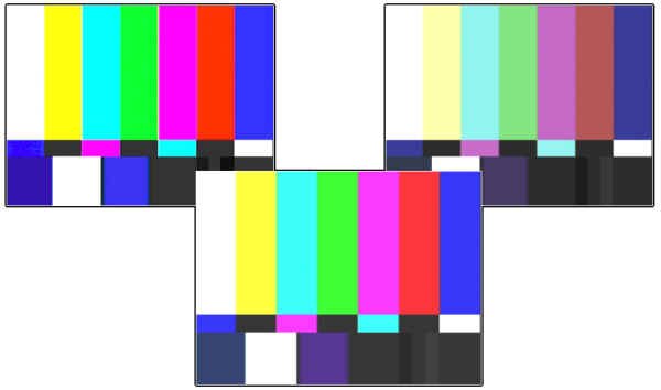
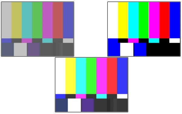
SMPTE Colour Bars
|
Saturation and Phase (Hue)
With an accurate set of colour bars, and viewing only the blue channel, you should see four blue bars of equal brightness and black between them. These bars should increase and decrease in brightness equally as the contrast is reduced and increased over its normal range - they should "track."
The left bar is the reference; the HUE affects the brightness of the inner two bars. The CHROMA affects the brightness of the rightmost bar and the two inner ones.
|
|
The sequence: first adjust the CHROMA, then the HUE so all four bars are equal with black in between. If the four bars do not track when you change the CONTRAST control, then the COLOUR HOLD needs adjustment and engineering should be notified.
The above test is much easier with SMPTE colour bars - the ones with the complementary colours directly below the regular ones. With these bars, one can check brightness differences without the effects of purity or shading getting in the way.
|
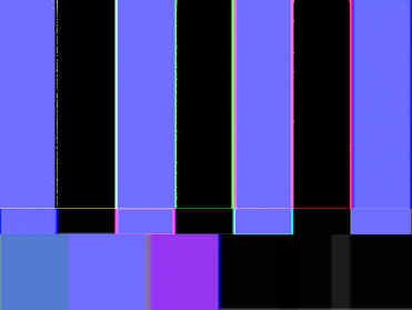
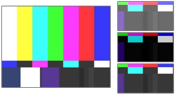
Colour bars, viewing only the blue channel
|
|
Closeup of lower right corner of colour bars, showing PLUGE (emphasized for clarity)
|
Brightness
Brightness is adjusted correctly when the active scanning lines are just at the point of visual extinction from your normal viewing distance. This is easy to set up with the PLUGE (Picture Line Up Generating Equipment), usually found in the lower right hand corner of the black area in the colour bar signal. It consists of two small vertical ribbons, one slightly greater than normal black and the other slightly less. The BRIGHTNESS is adjusted so the darker patch just merges with the reference black, but the brighter patch is still clearly visible, from where the monitor will be normally viewed, and under the normal ambient lighting conditions. As monitors are normally viewed from more than two feet away, be prepared to grow longer arms, enlist a fellow operator, or do a lot of walking back and forth.
|
Colour Temperature, Grey Scale Tracking
Colour temperature, along with grey scale tracking, is checked with a GIRTI.2 This is a box with a light source inside referenced to 6500 degrees Kelvin. You look at it through a hole in the front of the unit. In the centre of this reference is a circular window through which you can see a white square displayed on the monitor. The white at the bottom of colour bars will do; a centred white flag signal is better. The GIRTI is placed over the centre of the monitor white area and, while viewing the device from about 14 to 16 inches away (no squinting up close), colour temperature is adjusted so the outer ring matches the inner circle. Your eyes will go buggy after about five minutes of this, so take frequent breaks.
Here�s what to do:
|
Switch the monitor to MONOchrome. This gives you a black and white picture. Your goal is to try to achieve the best black and white picture possible, but displayed on your colour monitor. |
|
Using colour bars, adjust the BRIGHTNESS for correct PLUGE. |
|
Using the GIRTI, adjust the CONTRAST for a brightness match between the reference light and the white flag in the colour bars. |
|
Using the GAIN controls, adjust for a colour match. These controls also will affect the darker areas of the picture. Don't worry. |
|
Using the SCREEN controls, adjust for neutrals in the darker picture areas. These controls also will affect the lighter areas of the picture. |
|
Repeat the last two steps until you have neutrality all around. Eventually, you'll have proper monochrome colour bars staring at you. |
Monitor Matching
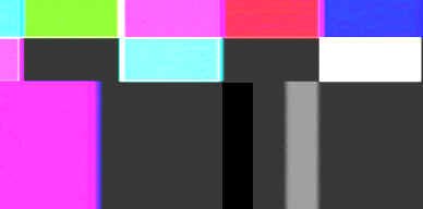
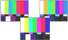
This is a common fault with colour monitors - they never appear to look exactly alike. To compound the problem, monitors cannot be completely checked using a static test signal such as bars. They may match on bars but do not match when scenes change. This is never more noticeable than when you put a colour background generator in several monitors and amaze yourself at the various hues presented to you from just one colour. Cyan and magenta are particularly difficult to match.
This may happen for several reasons: sensitivity to light and dark scene changes, incorrect RGB decoding, or even a defective picture tube.
So, perform each of these steps with each of the monitors you're trying to match, in turn:
|
Adjust for colour saturation and hue, brightness, colour temperature, and greyscale tracking, as discussed earlier. |
|
Ensure you're in colour mode on all monitors, and readjust for any minor discrepancies with brightness (use PLUGE), phase (use the yellow and cyan bars), and saturation (use the red and magenta bars). |
|
Display moving pictures or a background generator. If they don't match, double check your saturation and phase settings. |
|
When optimizing the monitors for a match, one must know when to call it "close enough for television." You'll only get frustrated if you try for perfection. Let experience be your guide. |
Black and White Monitors
Don't forget that black and white monitors need to be set up properly, too. You should set up brightness with the PLUGE, and set up contrast with a GIRTI.
A Few Notes on Comb and Notch Filters
We've all seen the switches on professional monitors and some high-end consumer products: "Comb Filter," "Notch Filter," "Noise Reduction," "Sharpness," Which switches should you turn on or off? Who knows?
The Comb
The comb filter removes the colour information from the luminance information. This gives the appearance of a sharper picture. You�ll also eliminate the problem effect known as "cross-colour," which appears as a rainbow pattern whenever there are closely spaced lines (the "colour fringes in the sportscaster�s checked suit" syndrome).
But you�ll get some NTSC artifacts like "dot crawl". You'll see this on any hard vertically-based chroma transitions. If you want to see some dot crawl, just look for anything in the picture that has chroma on one scan line and not the next, for instance, a red "underline" in graphics. You should see funny little "dots" moving sideways most noticeably along the bottom edge.
So, you can live with the colour fringes, or put up with the dot crawl but also make the picture look a little sharper, depending which way you flip the comb filter switch.
The Notch
The notch filter does just what the name implies - within the luminance information, it "notches" out a band of frequencies (specifically, those at 3.58 MHZ - colour subcarrier). This gets rid of the comb filter "dot crawl" mentioned above, but, like any filter, it isn�t perfect; unfortunately, it also makes your picture softer.
Deciding which setting to use for the notch filter switch is up to you: if the dots bother you, run with the notch "on." If you prefer more resolution, run with the notch "off."
Noise Reduction
Noise reduction has a somewhat more severe effect. The noise reduction removes low level detail from the picture, which (the designers hope) is mostly noise. It also can lose some picture detail, and often leaves things looking smeary. Most "broadcast types" aren�t too fond of noise reduction systems.
What To Flip?
With broadcast monitors, the notch filter can normally be left in. Because of the quality of the signals coming in, as well as the high-quality design of the monitor itself, the sharpness isn't affected all that much. In general, if you normally sit back, say, eight feet or so from the set, you probably won't be bothered much by the comb filter.
At home, do what pleases you most. If you like "lots of detail" then crank up the sharpness and flip the switches that look good to you. It may drive your room mate nuts, though - they may prefer a "less crawly", more subtle television picture.
Look on the bright side...it�s probably a lot easier to decide on how to set up your TV than to come to a consensus between watching the hockey game, or MuchMusic...
So...are you totally bored? Well then...Try This At Home!
It�s Friday night, it�s 3:00 a.m., and you can�t sleep. What can you do? Why, you can line up your television set, of course! Find a station that�s running that perennial favourite of late nite programming, bars and tone. Now, look carefully at the colour bars and follow these directions.
| Tint (or Hue): The yellow bar should be a nice lemon yellow - no green or peach tones in it. The magenta bar (that�s the pinkish one) shouldn�t be purple or orange. Adjust until this is so. |
|
|
|
Colour: The bars shouldn�t be blasting with colour, but they shouldn�t be weak or pastel, either. Adjust to suit your eyes. |
| Brightness: Look for a PLUGE signal in the lower right corner. If the station�s bars don�t have one, find another station. Adjust the brightness so the "lighter than black" PLUGE bar is visible, but the "darker than black" one is invisible. |
|
|
|
Contrast: This is an "eye" adjustment. Not so high that things are blooming or smearing all over the place, but not so low to make things "dull" looking. You want bright, happy, smiling colour bars here.
|
Sharpness: Don�t make it too artificial looking, but a little "edge" on the bars is nice. You might want to switch to a late night episode of Gilligan�s Island to really check this, because it�s easier to see the effect on regular-type programming.
Now that you�ve set up your TV set...go to sleep, okay?
Things To Think About
Picture tubes are one of the last tubes that we have to deal with in the television world because they�re cheap and do the job well. They have an interesting internal structure that you should be aware of.
There are other technologies out there, though - be aware of them and some pros and cons of using them.
There�s no getting around having to use television monitors, so we should know how to line them up, at least the essentials - what the controls are for, and how they affect the picture.
Without properly lined up monitors, we�ve lost our quality control. You wouldn�t use a lousy set of speakers to monitor broadcast audio, would you?
1. CBC. Viewing Conditions for the Evaluation of Colour Television Pictures.
2. The originator of the concept was the Institut for RundfunkTechnik, and the G and I were added for German and Instrument. Hence, German Institut for RundfunkTechnik Instrument. This device is also affectionately known as the DIRTY GIRTI.